

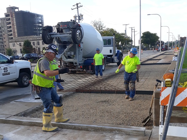

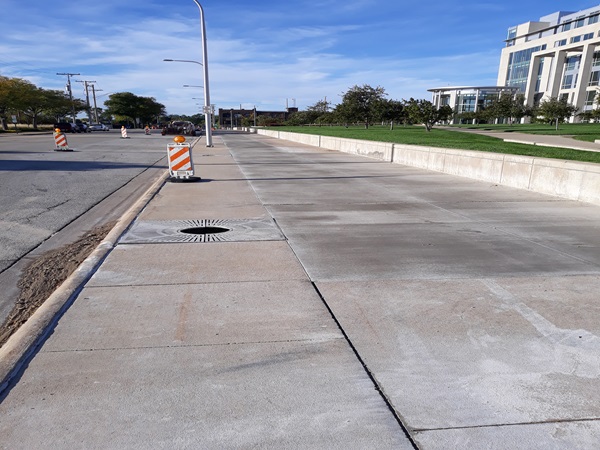
Following applicable IDOT standards, we replaced all cracked sidewalk sections in the front of the Courthouse utilizing ADA guidelines. Slabs were replaced with 6ft x 12ft sections and scored horizontally and vertically to control cracking. We then scored all other existing sections around the perimeter.
Work consisted of the rerouting and repair of an existing flush-out plumbing supply line. A leak detection system was installed with all required electrical hookups, and this was tied into the building’s BAS system. This line was directly above the building’s IT Room, so extreme planning and caution were considered. Work in the IT Room (above IT Equipment) was thoroughly coordinated with building management and the IT manager. Existing equipment remained in service and was protected from all construction operations. All equipment located under the water lines or drain lines was secured and protected with thick plastic. The bottom had to be left open so the equipment could breathe and not overheat.
The scope of work for this U.S. General Services Administration contract includes the removal of thirteen aged motor control centers and replacement with new electrical distribution. Three of the motor control centers are located in the sub-basement, one is located in the basement, two are located on the 28th floor, four are located on the 29th floor and three are located on the 30th floor. The replacement distribution will be in-place replacement. There are two locations where the new distribution needs to be relocated to maintain code-required clearances. New distribution consists of power distribution panels and new stand-alone combination HOA starter disconnect switches.
All non-disruptive preparatory work for each of the six (6) shutdowns occurred during the week, and the shutdowns occurred over weekends (starting Friday at 6:00 PM and completed by Sunday at 12:00 PM). All shutdowns were heavily coordinated and scheduled four (4) weeks in advance, with approval from Property Management and the U.S. District Courts. Our subcontractor had twenty (20) employees who successfully completed the security clearance process in a short amount of time, and all twenty were in rotation for all six round-the-clock weekend shutdowns. The team leader was in constant communication with the entire team (20 members) during each shutdown, giving updates on all significant events.
Dust-control measures, as well as noise control measures were followed with zero complaints.
All work was performed during a (6) phase period, all on premium time, which included weekend and around-the-clock operations.
Work was completed ahead of schedule without any interruptions to the Federal Court system.
Scope included the rehabilitation of two (2) entrance revolving doors and the rehabilitation of the existing handicapped door. Work included removal of the existing revolving doors in their entirety for rehabilitation and set aside for reinstallation, as well as removal of terrazzo/setting beds to the deck as needed to reinstall the new concrete ring. Removal of a concrete ring and the revolving door speed controls for replacement, removal of existing handicapped door, hardware, and jambs and replace. Removal of the door operator for the handicapped door, removal of panel of stainless steel for investigation to determine the structural condition behind the wall.
Electrical work included verification that the existing wiring and supply are adequate for the door operator. Electrician pulled new control wiring in the existing conduit from handicapped push buttons to ensure proper operation. Disconnect and reconnecting electrical at existing two Revolving doors.
Project scope consisted of the removal and disposal of a UST in the basement of the parking garage. It was excavated, assessed for leaks, extracted and disposed of properly, and then the garage was repaired back to a usable facility.
The project included an environmental consultant to oversee the excavation, dewatering, tank and concrete removal and legal disposal. Once exposed during excavation, the tank was pressure washed, emptied and removed legally offsite. Ancillary work included the removal and legal disposal of hydraulic lines (after draining), piston/hydraulic concrete and line removals, soil sampling, new C.I.P. concrete, concrete wall patching, traffic coatings and pavement markings.
The project scope included the disassembly, remove and legally hauling off-site the existing Vehicle Ops Parking Shed and reconstruct a pre-fabricated building with reinforced concrete foundation, floor with steel-framed structure, coated steel wall panels, roof panel system, and building impact protection located in new location. The demolition included foundation removal located at the existing location, new interior electrical, engine block heater plug-ins and lighting as well as exterior supporting facilities. It also included electrical service, communications, access pavements and site improvements at the new location. Asphalt paving. Remediation of unforeseen soil conditions were encountered during the excavation for the new foundations.
The purpose of this contract was to replace (4 ea.) PVC tape tubes utilized for the two existing Aircraft Arresting Systems (AAS) on the main Airfield Runway at Volk Field. The project included the removal of 4 ea. existing PVC tubes, excavation, backfill with crushed and stabilized base course and soil, demolition and replacement of concrete saddles and pier caps used to support the new tube replacement. The existing ties and anchor bolts needed for the support of the new (4 ea.) 12-3/4-inch steel tubes, were adjusted with the new concrete support saddles and piers. In addition, mechanical, electrical, & controls needed for the operation of the tube tape was performed. The support pier caps and saddles for the existing tubes needed to be altered due to the change in diameter from the existing tape tube to proposed tape tube. The project also included asphalt and concrete shoulder pavement, grading, pavement markings, airport runway lighting and intercommunication with Tower Aircraft Control Center allowing work to proceed safely at an active airport runway.
The project is a design-build project for the replacement of mechanical equipment, associated controls, and piping at Building 89 Altus Air Force Base, Oklahoma. The work involves replacing existing BACnet DDC controls, VAV boxes, hydronic system piping and Air Handling Units (AHUs) 7, 8, 10 and 11 with new units and removing and reinstalling AHU 9 in Building 89. AHU-7 and AHU-8 are in the first-floor mechanical room, whereas AHUs 9, 10 and 11 are in the mechanical room at the 2nd floor mezzanine level. Louvers on the south side of the building will be removed temporarily during construction to provide access to the 2nd floor mezzanine. In addition to the work in Building 89, the central plant heating boiler in Building 88 will be replaced. Building 89 is a simulation training facility which operates 20 hours per day, 7 days a week, and we are please to have completed the original scope of work 6 months ahead of required completion.
The basis of this project was to sealcoat and repaint aircraft parking apron shoulders.
Full depth concrete repair on spot# 4 of aircraft parking apron. The area to repair is located west of spot# 4 on the aircraft parking ramp and is approximately 20SY of 14” thick concrete. Excavate and dispose of approx. 14” of concrete at an offsite location. Installation of base material disturbed/ removed during excavation and compact. Compaction of subgrade stone installed in 3” lifts or less to obtain a compaction rate of 95% through nuclear density testing. Sealing of all pavement joints disturbed or created during demolition or construction operations. Removal of paint and repainting all concrete surfaces on aircraft parking apron.
The contract called for a new make-up air unit (MAU) to be installed in place of the existing MAU in Building 308. The new MAU will be a 100% outdoor air unit with a hot water coil. The unit will be 5,000 CFM. The MAU will have a freezestat for freeze protection along with a modulating hot water control valve to maintain discharge air temperature, complete with necessary sensors, actuators and starters. A new exhaust fan was installed on the other side of the building in place of the existing exhaust fan. Ductwork, piping, valves, and accessories will be of high grade and quality and consistent with requirements of military installations of this nature and per International Mechanical Code (IMC), UFC 3-400-10N, and SMACNA standards. All suspended equipment will be isolated from the structure with vibration isolators. Piping, valves, and equipment shall be labeled and tagged for identification. HVAC: A 100% outdoor air make up air unit (MAU) was installed in place of the existing MAU. The new unit was mounted to the ceiling using threaded rod, unistrut and vibration isolators. The unit sits below the cross braces but is still above the floor of the mezzanine. Based on site observation, we felt that hanging the unit was the best option due to weight restrictions on the floor of the mezzanine.